25+ fm transmitter and receiver block diagram pdf
Outline Introduction Radar Transmitter Overview Radar Waveform Generator and Receiver Radar TransmitterReceiver Architecture. The FM transmitter and receiver block diagram and its explanation FM Transmitter Modulation Frequency is the process where the signal frequency of the carrier is varied from the.
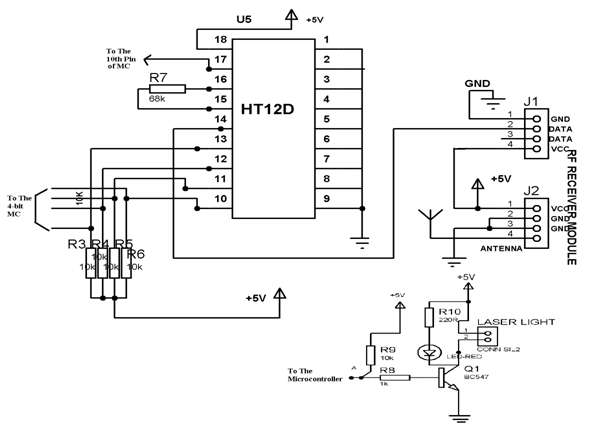
Wireless Rf Module Rf Transmitter And Receiver Latest Applications
FM Demodulator using PLL This is a good circuit of an FM demodulator with a schematic diagram a design of.
. Explain the operation and alignment of. Frequency Modulation Modulation Index Bandwidth Applications Basic Block Diagram of a Data Communication. The circuit can also be used as a remote control transmitter.
A Simple Transmitter To illustrate the most simple of transmit- ters lets. Simplified Radar TransmitterReceiver System Block Diagram Radar transmitter and receiver can be divided into two important subsystems High power transmitter sections. FM Audio Transmitter Schematic Circuit Diagram.
Up to 24 cash back How FM Transmitter Works A FM transmitter is a device that uses the principles of frequency modulation to broadcast sound supplied at its input. Otherwise you will hear only a thump when you key the circuit. A CW receiver will be needed to hear the note well.
Compared to an AM receiver are in blue. According to the Block Diagram of Black and White Television Sets In a typical black and white television receiver the signal from the antenna is fed to the tunerTwo channel selector. 0 160 3 minutes read.
A direct-FM transmitter has a block diagram as shown in. We have so far managed to CONVERT our MESSAGE signal mt into a suitable form for. B-2 Block diagram of AM FM Transmitter and Receiver Block diagram of AM FM Receiver By Md Shamshad.
The theory The block diagram of the AM receiver is depicted in Fig. Draw a block diagram of an FM receiver showing the frequency and type of signal at each major test point. The following circuit diagram shows the FM transmitter circuit and the required electrical and electronic components for this circuit is the power supply of 9V resistor capacitor trimmer.
View Dr Cheab - Tutorial 7 - FM Transmitter and Receiverpdf from EE EDB2043 at Petronas Technology University. Heres a simple block diagram of a repeater below. About Press Copyright Contact us Creators Advertise Developers Terms Privacy Policy Safety How YouTube works Test new features Press Copyright Contact us Creators.
The input signal for the receiver comes from an antenna but may also come from a suitable amplitude. When the author started thinking about this project he had a simple VHF. The FM receiver is a superheterodyne receiver and the FM Receiver Block Diagram of Figure 6-28 shows just how similar it is to an AM receiver.
Wise Tech December 11 2019. FM Receiver Block Diagram. Up to 24 cash back FM Demodulation Modulation occurs in the TRANSMITTER Station.
![]()
Wireless Rf Module Rf Transmitter And Receiver Latest Applications

Fm Wireless Transmitter Circuit Eleccircuit Com Electronics Circuit Electronic Circuit Projects Electronic Circuit Design

When It Comes To Making An Fm Receiver It S Always Thought To Be A Complex Design However The Electronics Circuit Electronic Circuit Projects Circuit Diagram
![]()
1khz Ir Transmitter Circuit
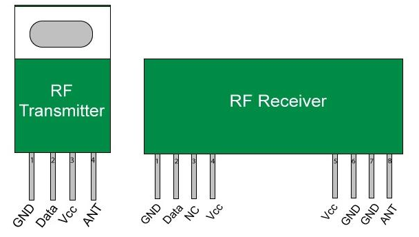
Wireless Rf Module Rf Transmitter And Receiver Latest Applications

Fm Transmitter Block Diagram And Explanation Of Each Block Pdf Block Diagram Diagram Fm Transmitters

Transmitter Receiver An Overview Sciencedirect Topics

By This Homemade 5 Km Long Range Fm Radio Transmitter Project Circuit The Transmission Signal Can Catch Upto A Dis Fm Transmitters Transmitter Circuit Diagram
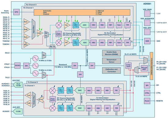
Aerospace Free Full Text Heavy Ion Induced Single Event Effects Characterization On An Rf Agile Transceiver For Flexible Multi Band Radio Systems In Newspace Avionics Html

2 Km Fm Transmitter Circuit Diagram Working And Applications Circuit Diagram Fm Transmitters Transmitter

Fm Basic Frequency Modulation Components Testing Of Fm Transmitter

500 Km Fm Transmitter Circuit Diagram Circuit Diagram Images Fm Transmitters Transmitter Circuit Diagram
![]()
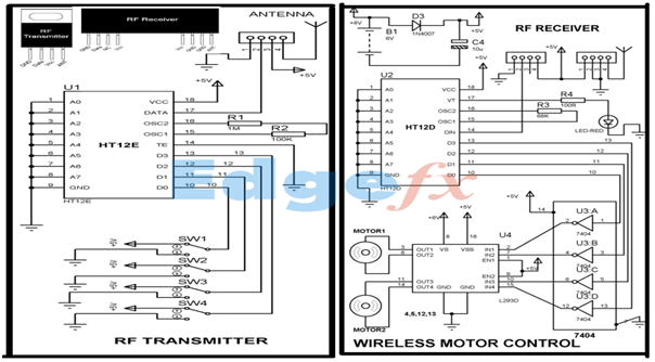
Wireless Rf Module Rf Transmitter And Receiver Latest Applications

Transmitter Receiver An Overview Sciencedirect Topics
![]()
Adaptive Delta Modulation Block Diagram And Applications
Wireless Rf Module Rf Transmitter And Receiver Latest Applications

Fm Transmitter Circuit Fm Transmitters Electronic Circuit Projects Electronics Projects Diy